Finger Weave Bridge (2016) - with Richard Boyd
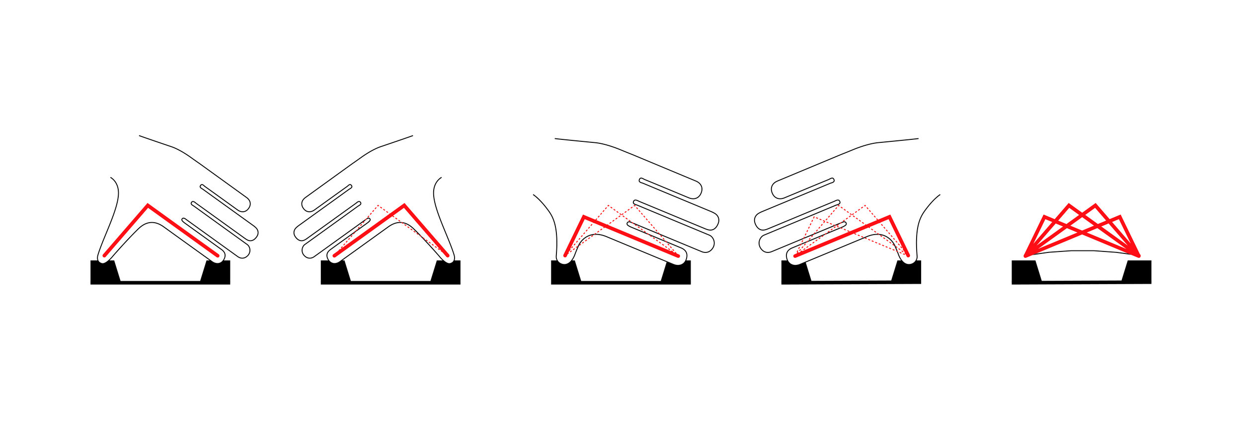
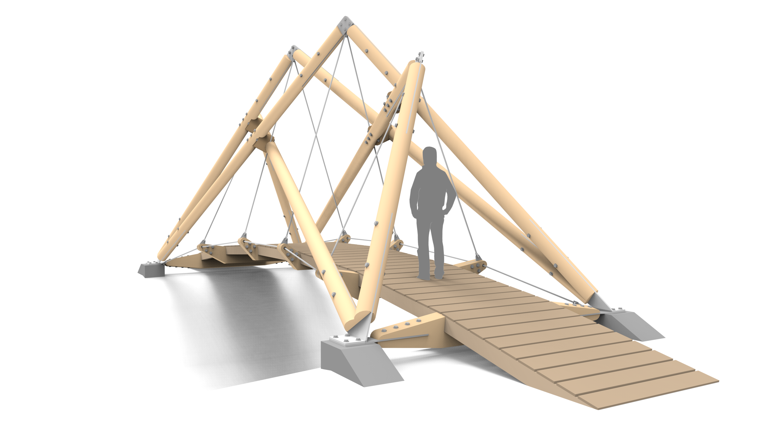
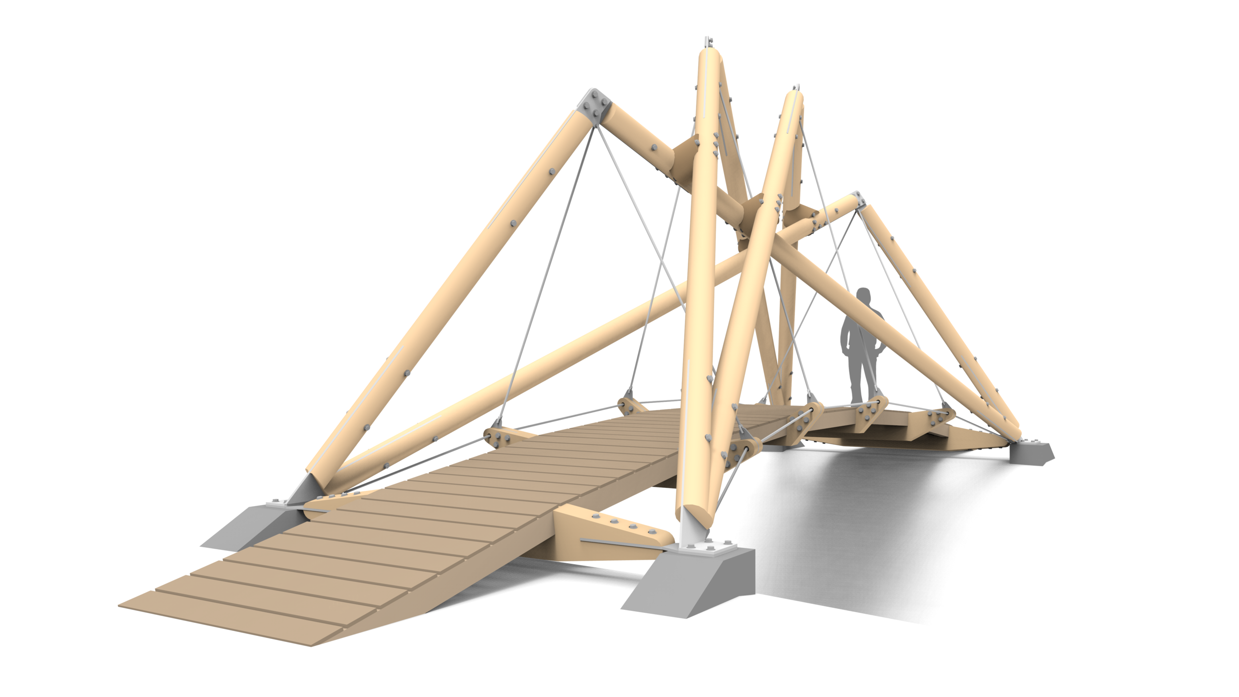
The concept is based on two pairs of hands interlocking with each other and reaching out towards the opposite bank. When viewed from the side, the lower slung elements appear to impede the crossing; it is only when in line with the deck that the user sees a clear passage. When crossing the bridge, the interlocking members create a fragmented canopy, as if the user is walking under the entwined fingers of two giants.
Structure
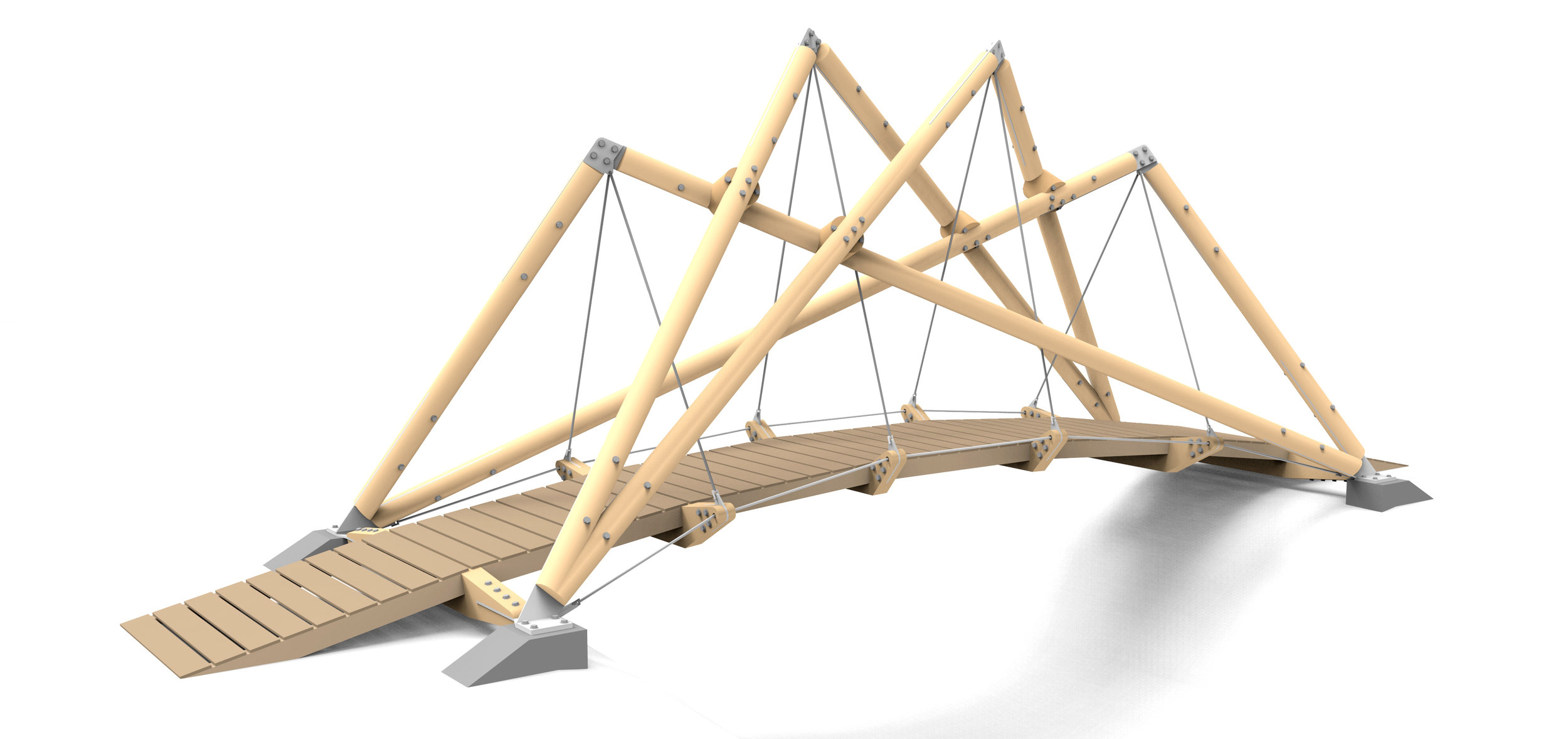
The Finger Weave structure consists of four overlapping and interwoven A-frames from which the deck of pre-fabricated timber cassettes and transverse timber ribs is suspended. The deck and A-frames are connected by raking steel hangers. The frames are paired, with pairs using each other for stability. The deck is restrained in both transverse and vertical directions by steel cables running between the bottom of the A-frames, via the ends of the transverse ribs. These cables resist the tendency of the A-frames to spread, internalising within the structure forces which otherwise would be taken by abutments.
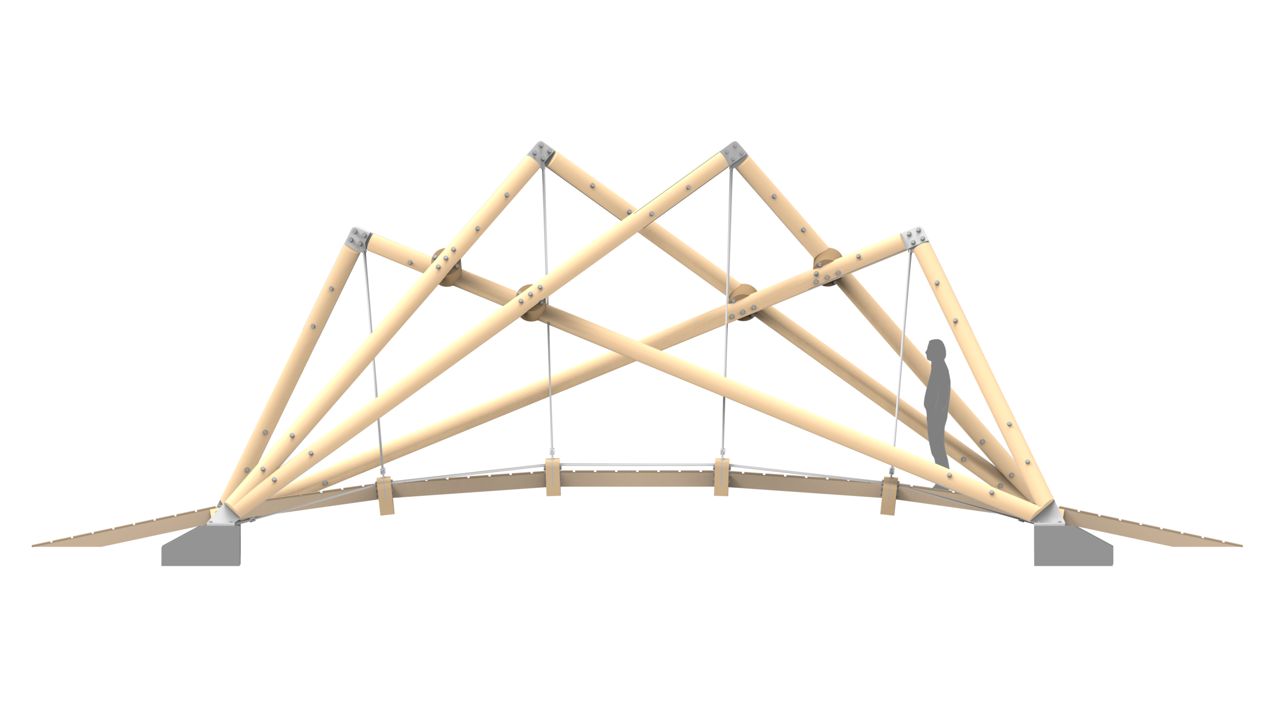
Vertical loads: Deck cassettes span between the transverse timber ribs, which themselves span between steel hangers. The hangers carry the tension loads to the apex of the A-frames, thence by compression to the foundations. The lateral component of the compression at the foundations is resolved by ties between footings in both the longitudinal and transverse directions. Given the frames are not aligned vertically, each has a tendency to move laterally under vertical loading. This is resisted by the frames being paired, so that they are mutually supporting; each props the other. This generates additional compression forces and some bending in the main A-frame members.
Lateral loads: Each deck cassette is braced to form a single rigid piece. They are connected to the timber ribs to form a continuous rigid deck. The ribs are restrained both by the tension cables running alongside the deck and by the non-vertical steel hangers.
Buildability
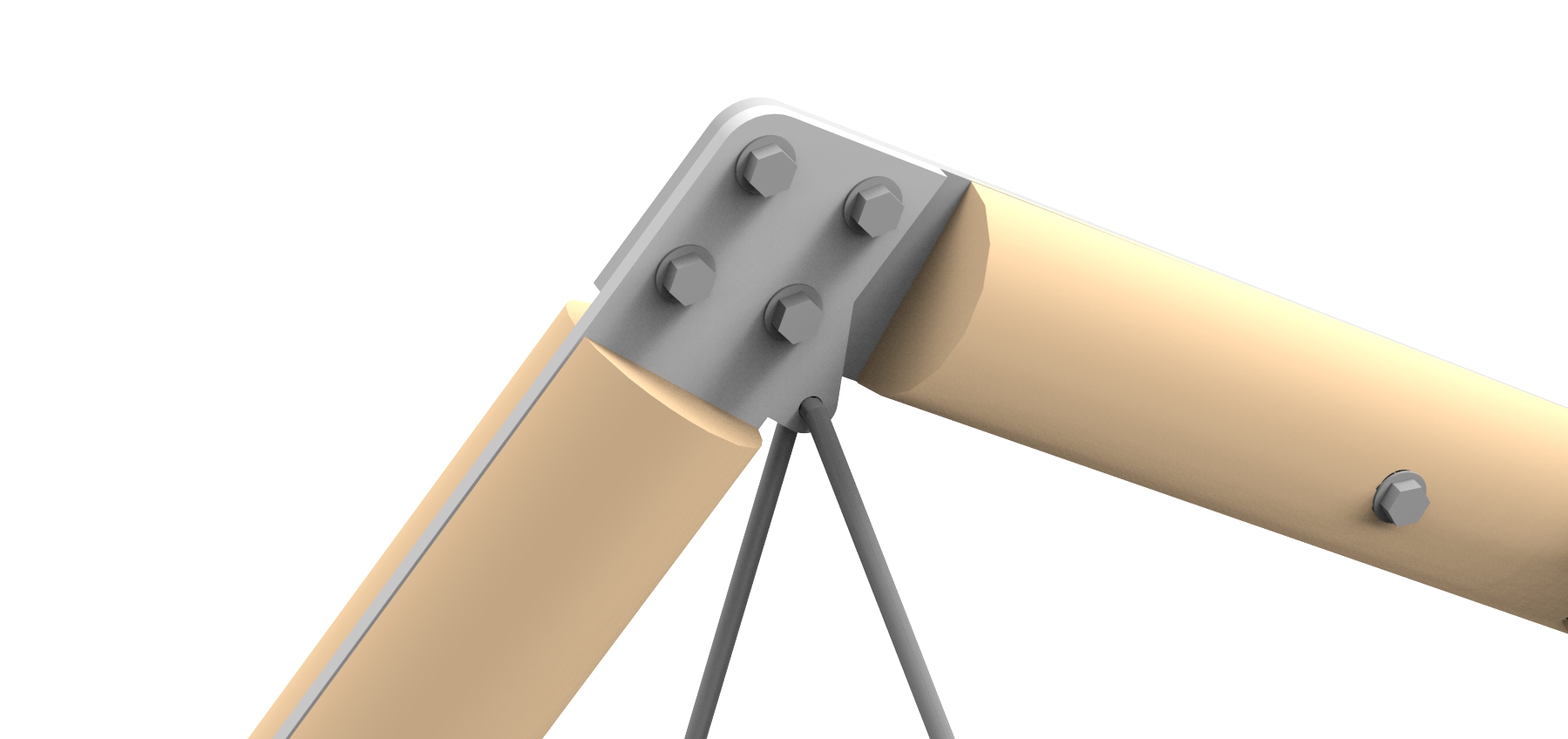
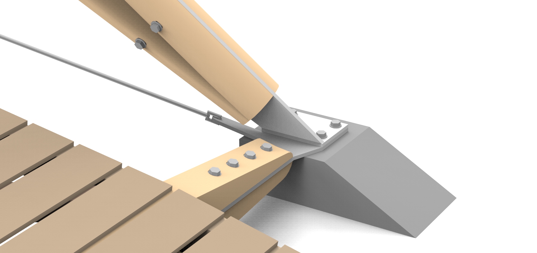
The A-frame apex connection detail, a critical one for the structural performance, becomes a hinge in the temporary case, allowing the
frame to be fed across the gap flat and pulled into place without heavy lifting equipment. The pairs of frames at the base connections share the same 2D plane, allowing the connection plate to be made from a single steel sheet. The baseplate is formed by folding this plate, obviating the need for any
welding. The hangers that support the deck are connected to the A-frame apex before erection, avoiding the need for working at height. The deck geometry is created from a 90 sided regular polygon, so can be fabricated as identical and pre-assembled cassettes, complete with finished floorboards in place.
Video: Model Rotation